
Why Does Tool Life Suddenly Drop? A Practical Guide to Cutting Tool Life, Wear Mechanisms, and Smarter Carbide Tool Selection
Table of Contents
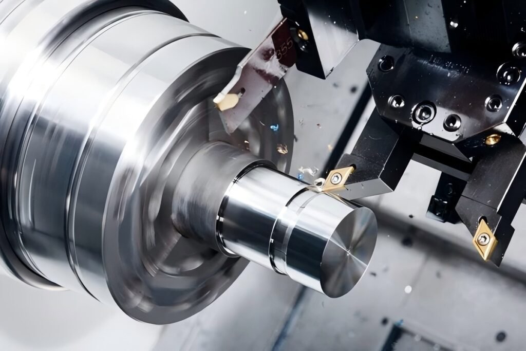
In modern machining, one question continues to challenge engineers, machinists, and purchasing managers alike:
Why does a cutting tool sometimes fail far earlier than expected?
Tool wear directly affects machining stability, surface finish, dimensional accuracy, and production cost. When a cutting tool loses its edge prematurely, it may cause burrs, poor surface quality, unstable cutting forces, and even catastrophic tool breakage.
Understanding tool life and tool wear mechanisms is therefore essential for any shop using solid carbide end mills, carbide drills, or indexable inserts.
Modern carbide tools are not simple cutting edges.
Their performance depends on a combination of:
- carbide substrate composition
- coating technology
- flute geometry
- chip evacuation design
- coolant delivery
- cutting parameters
If any of these factors are mismatched with the application, tool wear can accelerate dramatically.
So how exactly does tool wear occur? And how can manufacturers extend tool life while maintaining productivity?
Let’s explore.
What Exactly Is Tool Life?
In machining science, tool life refers to the cutting time from when a freshly sharpened or new cutting tool begins machining until its wear reaches a predefined limit.
This limit may be defined by:
- flank wear width
- deterioration of surface finish
- dimensional instability
- excessive cutting forces
- unacceptable burr formation
A tool may still physically cut material after reaching this limit, but the process quality and reliability decline rapidly.
There is also a broader concept known as total tool life.
This describes the entire working life of a tool, including multiple resharpening cycles, until the tool can no longer be used.
For example:
Tool Condition | Description |
New tool life | Cutting time from new tool to first wear limit |
Resharpened life | Life after tool regrinding |
Total tool life | Combined cutting time over entire lifespan |
In high-volume production, tool life must be predictable. A tool that fails unpredictably is often more costly than one with a slightly shorter but stable lifespan.
Why Do Cutting Tools Wear?
Cutting tools operate in one of the harshest environments in manufacturing.
During machining, the cutting edge experiences:
- extreme mechanical pressure
- friction with chips and workpiece
- high temperatures
- chemical interactions between tool and work material
These factors gradually remove material from the tool edge.
Tool wear generally falls into three main mechanisms:
1.Mechanical wear
2.Phase transformation wear
3.Chemical (diffusion) wear
The Three Primary Causes of Tool Wear
1. Mechanical Wear
Mechanical wear occurs mainly under low temperature and low cutting speed conditions.
It is caused by:
- friction between tool and workpiece
- abrasive particles in the material
- micro-scratching between contact surfaces
When hard particles in the workpiece slide along the tool surface, they can scratch microscopic grooves into the cutting edge.
This wear type is most common in:
- low-speed machining
- manual machining tools
- abrasive materials such as cast iron
2. Phase Transformation Wear
Phase transformation wear occurs when cutting temperature rises high enough to alter the microstructure of the tool material.
For example:
High-speed steel begins to lose hardness around 550–630°C.
If cutting temperatures exceed this range, the internal structure changes and the tool softens.
As hardness drops, wear accelerates rapidly.
This type of wear is common when:
- cutting speeds are too high
- cooling is insufficient
- tools are used beyond their temperature limits
3. Chemical (Diffusion) Wear
At even higher temperatures, chemical reactions occur between the tool and the workpiece material.
Elements such as:
- iron
- titanium
- cobalt
- tungsten
- carbon
may diffuse between the tool and the chip.
This diffusion changes the chemical composition of the cutting edge and can cause the tool to become softer or brittle, leading to rapid degradation.
Diffusion wear commonly occurs in high-speed machining using carbide tools, particularly when cutting alloy steels or high-temperature alloys.
What Do the Main Types of Tool Wear Look Like?
In real machining environments, tool wear does not appear randomly. It usually occurs in identifiable forms.
1. Flank Wear
Flank wear occurs on the clearance face of the tool and forms a wear band along the cutting edge.
This wear is typically measured by the parameter:
VB – flank wear width
Flank wear is the most common and most predictable wear form in machining.
It directly affects:
- dimensional accuracy
- surface finish
- cutting forces
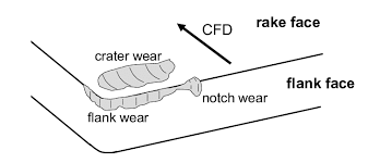
2. Crater Wear
Crater wear occurs on the rake face of the tool where chips flow across the cutting edge.
It forms a small depression known as a crater.
This wear type appears when:
- cutting speeds are high
- cutting temperatures rise significantly
- plastic metals are machined
Crater wear weakens the cutting edge and may eventually lead to edge breakage.
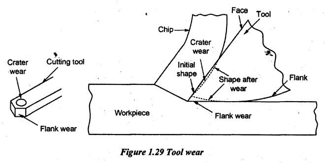
3. Combined Flank and Crater Wear
In many practical machining operations, both wear types appear simultaneously.
This is common when:
- cutting ductile metals
- chip thickness ranges between 0.1–0.5 mm
- cutting speed and load are moderate
When both wear types progress together, tool degradation accelerates significantly.
Common Tool Wear Types and Their Causes
Wear Type | Main Location | Main Cause | Typical Materials |
Flank Wear | Clearance face | Abrasion and friction | Steel, cast iron |
Crater Wear | Rake face | High temperature diffusion | Alloy steel |
Built-up Edge | Cutting edge | Adhesion of work material | Aluminum, stainless steel |
Notch Wear | Depth-of-cut line | Work hardening | Stainless steel |
Thermal Cracking | Edge surface | Temperature cycling | Interrupted milling |
How Does Tool Wear Develop Over Time?
Tool wear typically follows a predictable pattern consisting of three stages.
Stage 1 – Initial Wear Stage
When machining begins, wear increases rapidly.
This happens because:
- the tool surface contains microscopic irregularities
- the outer layer of the cutting edge may be less wear resistant
This stage is usually short.
Stage 2 – Normal Wear Stage
Once the initial irregularities are removed, wear stabilizes.
This stage is the most desirable operating period.
During this stage:
- wear progresses slowly
- cutting forces remain stable
- surface finish is consistent
Most productive machining occurs here.
Stage 3 – Rapid Wear Stage
Eventually, wear reaches a critical level.
At this point:
- friction increases
- cutting temperature rises sharply
- contact conditions worsen
Wear accelerates dramatically.
If machining continues beyond this stage, the tool may quickly fail or break.
Tool Wear Stages and Machining Characteristics
Wear Stage | Characteristics | Machining Stability |
Initial Wear | Rapid early wear | Moderate |
Normal Wear | Stable wear progression | Best cutting performance |
Rapid Wear | Accelerated wear | Unstable machining |
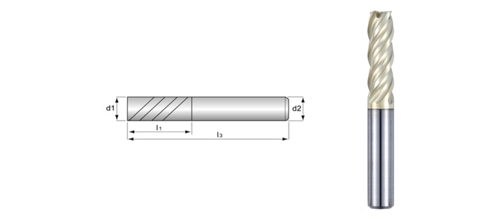
Which Carbide Tool Designs Help Extend Tool Life?
Modern carbide tools incorporate advanced design features to improve wear resistance.
Variable Helix End Mills
Variable helix designs reduce vibration and improve cutting stability in steel machining.
Advantages include:
- improved chip evacuation
- reduced chatter
- longer tool life
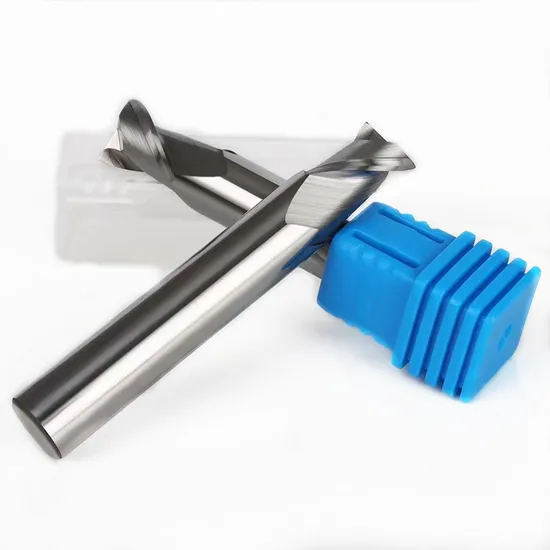
Polished Aluminum End Mills
Aluminum machining requires sharp edges and polished flute surfaces.
These features help prevent:
- chip welding
- built-up edge
- surface damage
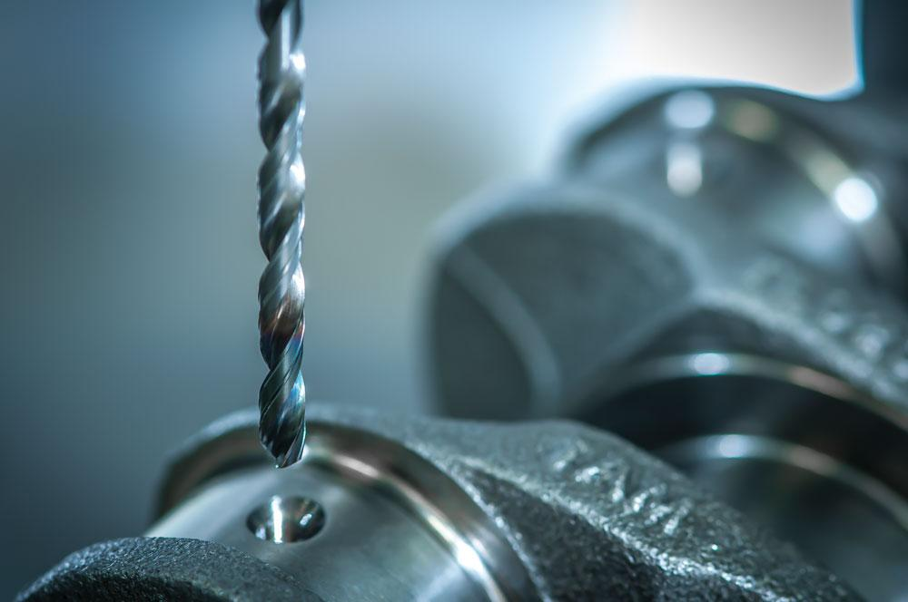
Coolant-Through Carbide Drills
For drilling applications, internal coolant channels improve:
- heat removal
- chip evacuation
- hole quality
This design is especially important in deep-hole drilling and stainless steel machining.
Recommended Tool Types for Different Materials
Material | Recommended Tool | Key Features |
Steel | 4-flute carbide end mill | High rigidity, wear-resistant coating |
Stainless Steel | Tough carbide end mill | Strong cutting edge |
Aluminum | 2-flute polished end mill | Large flute space |
General drilling | Solid carbide drill | Coolant-through design |
Deep hole drilling | Long carbide drill | High chip evacuation |
Final Thoughts: Tool Life Is a Balance of Design and Process
Tool life is not determined by a single factor.
Instead, it results from the interaction between:
- tool material
- coating technology
- cutting parameters
- cooling strategy
- workpiece material
By understanding the mechanisms of tool wear, manufacturers can select the correct cutting tools and optimize machining conditions.
This leads to:
- longer tool life
- better surface quality
- improved machining efficiency
- lower manufacturing costs
In modern machining, controlling tool wear is not just about protecting tools—it is about maximizing productivity and reliability.


