
Why Does Your Face Milling Surface Finish Suddenly Get Worse?
Table of Contents
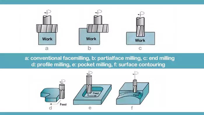
In modern machining, face milling is one of the most common operations used to create flat surfaces on components such as mold plates, machine bases, automotive parts, and structural components.
However, many machinists encounter a frustrating problem during face milling operations:
- The surface finish suddenly becomes rough
- Tool wear increases unexpectedly
- The cutter vibrates even under stable cutting conditions
Why does this happen?
Even when using high-quality inserts and rigid machines, the root cause is often something small but critical:
Cutting edge runout.
This article explains:
- What cutting edge runout really is
- Why it dramatically affects surface quality
- How feed rate interacts with insert geometry
- Why wiper inserts are one of the most effective solutions
If you want to improve your face milling surface finish while maintaining high productivity, this guide will help.
What Is Cutting Edge Runout in Face Milling?
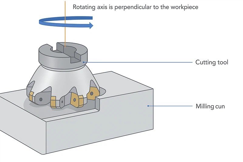
When inserts are mounted on a face milling cutter body, each cutting edge should ideally lie on the same rotational plane.
However, due to factors such as:
- Insert manufacturing tolerances
- Pocket accuracy
- Clamping force variations
- Tool holder precision
some inserts may sit slightly higher or lower than others.
This deviation is called cutting edge runout.
Runout means that not every insert removes the same amount of material.
Instead:
- One insert may do most of the cutting
- Others only rub the surface
- Some barely touch the workpiece
This imbalance is the starting point of many machining problems.
How Much Runout Is Acceptable?
In most face milling operations, acceptable runout should be extremely small.
Below is a typical tolerance reference.
Cutter Diameter | Recommended Runout |
≤ 80 mm | ≤ 0.02 mm |
80–160 mm | ≤ 0.03 mm |
≥ 160 mm | ≤ 0.05 mm |
Even a small deviation can drastically change the cutting behavior.
For example, if one insert protrudes 0.03 mm more than the others, it will remove most of the material and experience excessive wear.
Why Does Runout Destroy Surface Quality?
Have you ever seen milling surfaces with uneven feed marks?
Or experienced sudden chatter even though cutting parameters are correct?
Runout is often the hidden cause.
Uneven Load Distribution
In an ideal face milling operation:
- Each insert shares the cutting load equally
- Cutting forces remain balanced
- Tool life is maximized
But when runout exists:
- One insert carries the majority of the load
- Other inserts barely cut
- The cutting process becomes unstable
This leads to vibration and inconsistent surface quality.
Surface Finish Deterioration
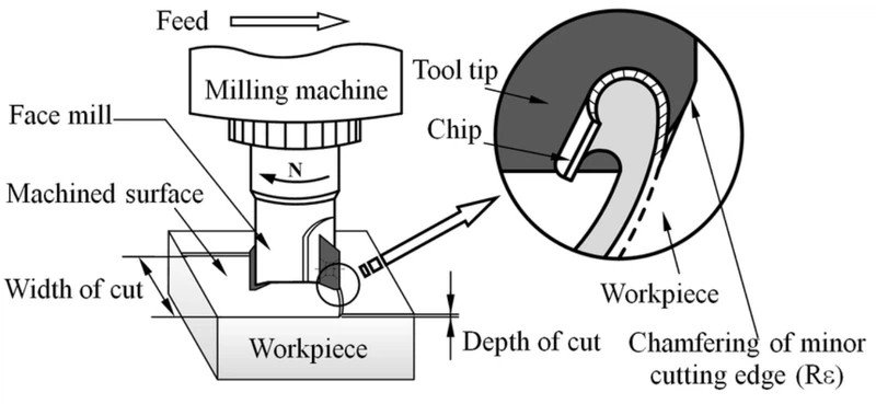
Surface finish in face milling depends heavily on consistent chip formation.
When runout exists, the machining marks left by each insert vary in height.
The result:
- Irregular feed marks
- Increased surface roughness
- Visible machining lines
The surface becomes uneven because different inserts remove material at different depths.
Accelerated Tool Wear
Runout not only affects the surface finish — it also shortens tool life.
When one insert performs most of the cutting:
- Local temperature increases
- Wear concentrates on one edge
- Micro-chipping occurs
This often leads to premature insert failure.
How Does Feed Per Tooth Influence Surface Finish?
Surface finish is also closely related to feed per tooth (fz).
The relationship between feed rate and insert geometry is critical.
If the secondary cutting edge length is greater than the feed per tooth, the surface will be smoother.
But if the feed is too large, the insert cannot properly smooth the surface.
The following table illustrates this relationship.
Feed per Tooth (fz) | Typical Surface Quality |
Very small (≤0.05 mm/tooth) | Excellent finish |
Moderate (0.05–0.20 mm/tooth) | Stable finish |
Large (>0.20 mm/tooth) | Rougher surface |
This is why high productivity milling often requires special insert designs.
And this is where wiper inserts come in.
What Is a Wiper Insert — And Why Is It So Effective?
A wiper insert is a specially designed insert used in face milling cutters to improve surface finish without reducing feed rate.
Unlike standard inserts, a wiper insert has:
- A longer secondary cutting edge
- A slightly protruding position
- A flatter cutting geometry
Its main role is simple:
It smooths the surface after the main cutting inserts remove material.
This allows machinists to maintain high feed rates while still achieving excellent surface finish.
How Are Wiper Inserts Installed in a Face Milling Cutter?
Correct installation is essential for the wiper insert to function properly.
The typical configuration includes:
- 1–2 wiper inserts installed on the cutter
- Positioned among standard inserts
- Slightly higher than normal inserts
Below is a typical installation rule.
Installation Parameter | Typical Value |
Number of Wiper Inserts | 1–2 pieces |
Height Difference | 0.03–0.10 mm |
Edge Length | Longer than feed per tooth |
The exact values depend on:
- Cutter diameter
- Feed rate
- Insert geometry
Why Must the Wiper Edge Be Slightly Higher?
You might wonder why not install all inserts at the same height.
The reason is simple.
The wiper insert must perform the final finishing cut.
By protruding slightly (typically 0.03–0.10 mm), it removes the remaining peaks left by the main inserts.
This results in:
- Smooth surfaces
- Uniform machining marks
- Reduced roughness
When Should Multiple Wiper Inserts Be Used?
In large cutters or high-feed milling applications, one wiper insert may not be enough.
Consider using two or three wiper inserts when:
- Cutter diameter is large
- Feed per revolution is high
- Surface finish requirements are strict
However, caution is necessary.
If multiple wiper inserts are installed, their runout must also be controlled carefully.
Otherwise, vibration may occur.
Practical Example: Face Milling with and without Wiper Inserts
Let’s compare two real machining scenarios.
Parameter | Standard Inserts | With Wiper Insert |
Feed Rate | 0.20 mm/tooth | 0.20 mm/tooth |
Surface Roughness | Ra 3.2 | Ra 0.8 |
Tool Wear | Higher | Lower |
Surface Appearance | Visible feed marks | Smooth finish |
As shown above, the difference can be dramatic.
By simply adding a wiper insert, surface roughness can improve by up to 3–4 times.
Insert Materials: Why Wear Resistance Matters
Wiper inserts continuously contact the machined surface.
Therefore they must have:
- Excellent wear resistance
- High edge stability
- Strong carbide substrate
Typical materials include:
- Fine-grain carbide
- PVD coated carbide
- AlTiN coated inserts
These materials help maintain edge sharpness during long machining cycles.
Best Practices to Achieve Perfect Face Milling Surfaces
If you want stable machining results, consider the following recommendations.
Ensure Accurate Insert Mounting
Clean insert pockets and tighten screws properly to minimize runout.
Use High-Precision Cutter Bodies
Poor cutter body accuracy can introduce runout before machining even begins.
Optimize Feed Per Tooth
Match feed rate with insert geometry and edge length.
Use Wiper Inserts
For high productivity and good surface finish, wiper inserts are essential.

Conclusion: Small Runout, Big Impact
Cutting edge runout is one of the most underestimated factors in face milling.
Even tiny deviations can cause:
- Poor surface finish
- Tool vibration
- Uneven insert wear
- Reduced tool life
By combining:
- precise insert installation
- optimized feed parameters
- properly positioned wiper inserts
manufacturers can dramatically improve machining stability and surface quality.
In modern high-efficiency milling operations, wiper inserts have become an essential solution for achieving both productivity and precision.


