 Skip to content
Why Is Chip Control So Critical in Steel Turning?
Table of Contents
In modern CNC turning, chip control is not a minor detail — it is a decisive factor in safety, productivity, automation stability, and tool life.
Have you ever faced:
- Long ribbon chips wrapping around the toolholder?
- Surface scratches caused by chip re-cutting?
- Machine alarms due to chip congestion?
- Inconsistent tool life at higher cutting speeds?
If yes, the root cause is often poor chip control matching — not necessarily the insert grade itself.
This article provides a structured, engineering-based analysis of:
- Chip morphology in steel turning
- The influence of cutting speed (vc) on chip control range
- The impact of coolant vs. dry cutting
- How to select the correct chipbreaker geometry
- Practical parameter windows for stable chip breaking
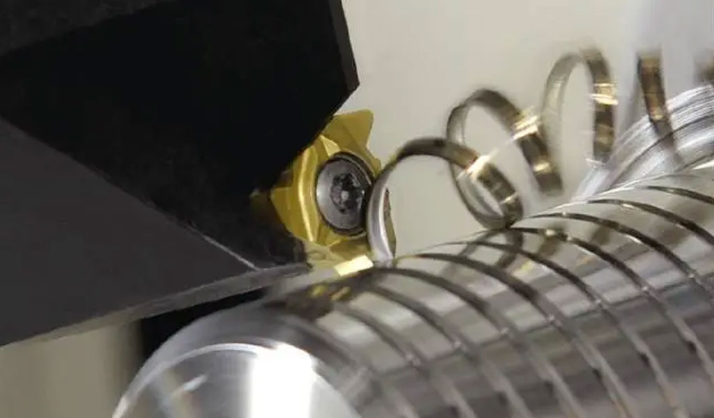
What Determines Chip Shape in Steel Turning?
Chip formation depends primarily on:
- Depth of cut (ap)
- Feed rate (f)
- Cutting speed (vc)
- Insert chipbreaker geometry
- Coolant condition
When machining medium carbon steels (e.g., 45# / AISI 1045 / S45C), chip shape changes significantly depending on chip thickness and thermal conditions.
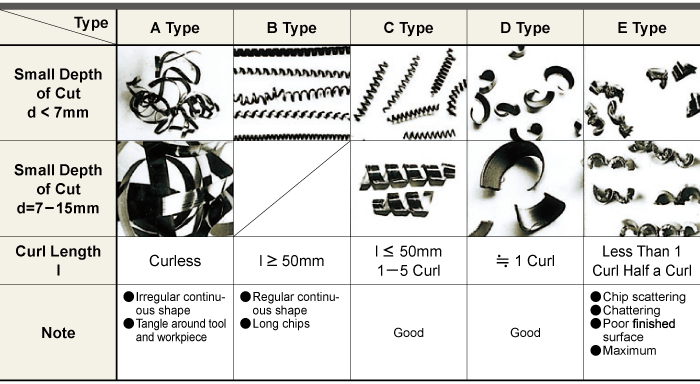
Typical Chip Morphology Classification
Chip Type | Description | Stability | Risk Level |
A | Long irregular ribbon | Very unstable | High (wrapping) |
B | Regular long spiral | Unstable | Medium–High |
C | Short spiral (1–5 turns) | Acceptable | Medium |
D | Half-circle (~1 turn) | Good | Low |
E | Short fragmented chips | Ideal | Very Low |
Key Insight:
Chip types C–E are typically considered acceptable in production.
Chip types A and B are unacceptable in automated CNC environments.
But what determines which type you get?
How Does Depth of Cut Affect Chip Control?
Chip thickness is largely proportional to feed rate and depth of cut.
When ap increases:
- Chip cross-section increases
- Chip rigidity increases
- Curling becomes stronger
- Breaking becomes easier
Recommended Feed Windows by Depth of Cut
Depth of Cut (ap) | Feed Range (mm/rev) | Expected Chip Type | Recommended Chipbreaker |
< 2 mm | 0.10–0.25 | A–C | Light cutting geometry (LF type) |
2–5 mm | 0.20–0.35 | C–D | Medium chipbreaker (MF type) |
5–10 mm | 0.30–0.50 | D–E | Heavy chipbreaker (HF type) |
If you reduce feed excessively at larger depths, chips may return to continuous type.
So the real question is:
Are you adjusting feed together with depth of cut — or independently?
Does Higher Cutting Speed Always Improve Productivity?
Intuitively, higher cutting speed increases productivity. But what happens to chip control?
Let’s examine chip control windows at different cutting speeds.
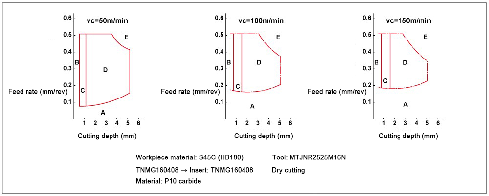
Chip Control Window vs Cutting Speed
Based on typical industrial tests in steel turning:
Cutting Speed (m/min) | Stable Chip Control Window (Feed Range mm/rev) | Chip Control Area Size |
50 | 0.15–0.40 | Wide |
100 | 0.20–0.35 | Medium |
150 | 0.25–0.32 | Narrow |
Why Does the Window Shrink?
As cutting speed increases:
1.Cutting temperature increases
2.Steel plasticity increases
3.Chips become softer and more ductile
4.Chipbreaker struggles to fracture chip
5.Continuous chips reappear
This is why in high-speed turning:
- Feed precision becomes critical
- Chipbreaker design must be optimized
- Coolant strategy becomes important
So instead of asking:
“Can I run faster?”
You should ask:
“Is my chipbreaker designed for this speed range?”
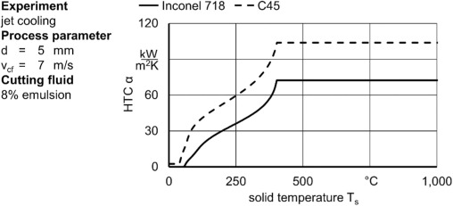
Dry vs Wet Cutting — Does Coolant Really Change Chip Control?
Many shops assume coolant only affects tool life. But it also significantly affects chip formation.
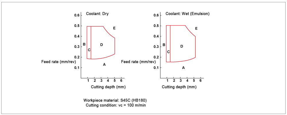
Dry vs Wet Comparison (Same Cutting Speed: 100 m/min)
Condition | Thermal State | Chip Ductility | Chipbreaking Range |
Dry Cutting | High temperature | High ductility | Narrow |
Wet Cutting (Emulsion) | Reduced temperature | Lower ductility | Wider |
Engineering Explanation
Coolant reduces:
- Shear zone temperature
- Secondary deformation temperature
- Built-up edge formation
Lower temperature → higher brittleness → easier fracture.
Therefore:
At identical speed, wet cutting often provides a larger chip control window.
But does that mean coolant is always better?
Not necessarily.
In coated carbide turning inserts (e.g., PVD TiAlN or CVD Al2O3 coatings), thermal shock must also be considered.
So the correct strategy depends on:
- Insert grade
- Coating type
- Workpiece hardness
- Machine capability
How Do Chipbreaker Geometries Actually Work?
Chipbreakers are not decorative grooves — they are precisely engineered deformation systems.
A chipbreaker works by:
1.Forcing chip to curl
2.Increasing bending stress
3.Creating tensile stress on outer surface
4.Causing fracture
Let’s examine three common geometry types in steel turning inserts.
Chipbreaker Type | Application Range | Feed Sensitivity | Typical Use |
Light (LF) | Finishing | High | ap < 2 mm |
Medium (MF) | General turning | Medium | 2–5 mm |
Heavy (HF) | Roughing | Low | >5 mm |
What Happens If You Use the Wrong One?
- Heavy breaker at small feed → no chip contact → ribbon chips
- Light breaker at heavy feed → chip overflows groove → uncontrolled break
Matching feed and breaker geometry is essential.
Case Example: Medium Carbon Steel Turning
Let’s consider:
- Material: AISI 1045
- Hardness: HB180
- Insert: CNMG120408, P25 grade, MF chipbreaker
- Coolant: Emulsion
Stable Parameter Window
Parameter | Value |
Cutting Speed | 120 m/min |
Depth of Cut | 3 mm |
Feed | 0.28 mm/rev |
Chip Type | D–E |
Tool Life | Stable (VB < 0.3 mm at 15 min) |
When speed increased to 160 m/min (same feed):
- Chip returned to C-type spiral
- Chip control less stable
- Surface finish fluctuated
Why?
Because chip control window narrowed at higher speed.
What Are the Real Production Recommendations?
If you see long continuous chips:
- Increase feed slightly
- Reduce cutting speed moderately
- Switch to stronger chipbreaker
- Consider coolant activation
If chips are too fragmented and surface roughness increases:
- Reduce feed
- Slightly increase speed
- Use lighter chipbreaker
For automated production:
Aim for consistent E-type short broken chips.

Final Thoughts — Chip Control Is a System, Not a Single Parameter
Chip control is the result of:
- Speed (vc)
- Feed (f)
- Depth (ap)
- Chipbreaker geometry
- Coolant condition
- Workpiece material behavior
When one variable changes, the entire chip control window shifts.
Instead of asking:
“Why is my insert failing?”
Ask:
“Is my parameter window aligned with this chipbreaker design?”
Conclusion
In steel turning:
- Increasing cutting speed narrows chip control range.
- Coolant widens chipbreaking window.
- Feed rate is the most sensitive chip control parameter.
- Chipbreaker geometry must match depth and feed.
- Stable chip control improves safety, automation, and tool life.
Understanding these relationships transforms chip control from a trial-and-error problem into a predictable engineering process.


