
Beyond the Edge: Are Your Cutting Tools Dying Prematurely? A Deep Dive into 9 Modes of Wear
Table of Contents
As a CNC professional, you’ve likely asked yourself: “Why did that carbide insert fail after only 50 parts when it should have lasted 200?” In the high-stakes world of precision machining, tool wear isn’t just a technical inevitability; it is a financial drain. Every micron of tungsten carbide lost to friction or heat is a direct hit to your bottom line. But what if you could “read” your tools like a book? Understanding the nuances between chemical erosion and mechanical fatigue can be the difference between a profitable shift and a scrap-bin disaster.
In this definitive guide, we analyze the nine specific forms of tool wear, investigate the latest coating technologies, and provide actionable strategies to reclaim your tool life.
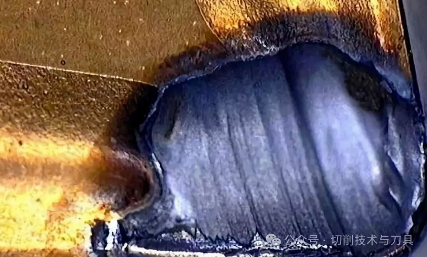
The Hidden Cavity: Is Crater Wear Sabotaging Your High-Speed Runs?
Typically appearing on the rake face, Crater Wear is the silent assassin of high-speed steel and carbide tools. But why does it form a “lunar crater” right behind the cutting edge?
The Science of Diffusion
This is primarily a chemical phenomenon. At high temperatures, carbon atoms from the tool matrix literally dissolve into the chip and are carried away. This is most prevalent when machining low-carbon steels at aggressive speeds.
- The Warning Sign:The crater grows until it weakens the tool tip, leading to a catastrophic “break-through.”
- The Pro-Active Fix:* Transition to CVD-coated (Chemical Vapor Deposition)inserts with a thick Al₂O₃ (Aluminum Oxide) layer.
Reduce cutting speed to keep the interface temperature below the diffusion threshold.
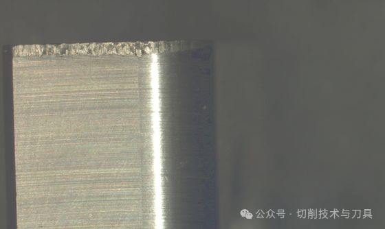
Flank Wear: Is Your “Normal” Wear Actually Costing You Precision?
If you see a uniform wear land on the part of the tool that rubs against the workpiece, you’re looking at Flank Wear. While it’s considered “normal,” is your VB (Wear Land Width) growing too fast?
Abrasive Attrition
This is caused by hard particles in the workpiece (like carbides in alloy steel) grinding away the tool. As Flank Wear increases, so does the cutting force and the friction, leading to dimensional instability.
Plastic Deformation: Is Your Tool Tip “Wilting” Under Pressure?
When the cutting edge begins to sag, dip, or mushroom outward, you are witnessing Plastic Deformation. Have you pushed your feed rates beyond the material’s yield strength?
Variable | Impact on Plastic Deformation | Recommended Adjustment |
Temperature | Primary Driver (Softens Matrix) | Increase Coolant Pressure |
Cutting Force | Secondary Driver (Physical Squeeze) | Reduce Feed Rate ($f_n$) |
Substrate Hardness | Resistance Factor | Move to a Lower Cobalt Grade |
The Strategy:
Use “Hot Hardness” materials. Brands like Sandvik Coromant’s GC4425 or Kennametal’s KCP25B use specialized gradients to maintain tip integrity even at $1000^\circ C$.
Thermal Cracking: Are You “Shocking” Your Carbide to Death?
Ever noticed small, comb-like cracks perpendicular to the cutting edge? That’s Thermal Cracking. Why does it happen more often in milling than in turning?
The “Pulse” Problem
In milling, the tool enters and leaves the cut, heating and cooling rapidly. This expansion and contraction create internal stress.
- The Paradox:Sometimes, less coolant is better. In heavy interrupted cuts, switching to dry machining with compressed air prevents the “thermal shock” caused by coolant hitting a glowing-hot edge.
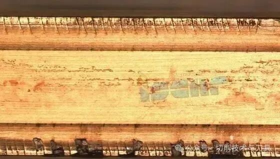
Coating Delamination: Why Is Your “Armor” Peeling Off?
When the protective coating (TiN, TiAlN, etc.) flakes away to reveal the raw carbide, your tool is defenseless. Are you machining “gummy” materials like Grade 5 Titanium or 304 Stainless?
- The Mechanism:The chip welds to the coating. When the chip breaks away, it takes a piece of the coating with it.
- The Solution:Use PVD (Physical Vapor Deposition)coatings. PVD is thinner and tougher than CVD, offering better adhesion for the sharp edges required in sticky materials.
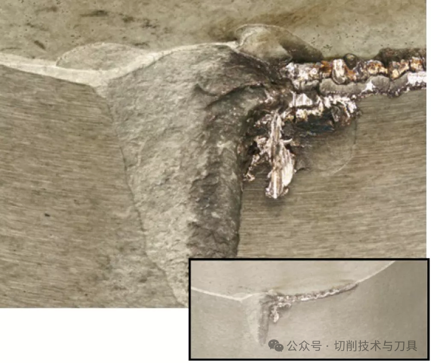
Chipping: Is it a Micro-Fissure or a Total Failure?
Chipping involves small fragments breaking off the edge. Can you still use the tool? Perhaps—but your surface finish will suffer.
Comparing Mechanical Failures
Feature | Chipping | Fracture |
Visual | Small notches on the edge | Large section of the tip missing |
Usability | Can often be used for roughing | Immediate Scrap |
Main Cause | Excessive vibration or hard spots | Overload or “Crash” |
Notch Wear: The “Ap” Boundary Problem
Notch Wear occurs specifically at the depth-of-cut line . Why is the wear so localized?
It’s a combination of the work-hardened “skin” of the previous pass and atmospheric oxidation.
- The Pro Tip:Use a variable depth of cutor a larger lead angle (entering the work at an angle rather than 90°) to spread the wear along a longer section of the edge.
Total Fracture: The Machine Shop’s Nightmare
A Fracture is a sudden, catastrophic failure. Did you check your tool holder’s runout?
Fractures are rarely the fault of the tool alone.
They usually point to:
1.Improper Setup: Is the overhang too long?
2.Wrong Grade: Are you using a “Hard/Brittle” grade where you need a “Tough” grade?

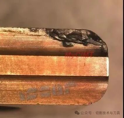
Built-Up Edge (BUE): Is Your Tool Growing or Shrinking?
Perhaps the most frustrating phenomenon: the workpiece material welds itself to the tool tip, creating a “fake” cutting edge.
Why is BUE Dangerous?
When the BUE eventually breaks off, it often takes part of the tool’s carbide with it, leading to a jagged edge.
- The Fix:Increase your speed!BUE typically occurs at lower cutting speeds. By increasing , you generate enough heat to keep the chip fluid, preventing it from cold-welding to the rake face.
Conclusion: Turning Data into Tool Life
Understanding these nine modes of wear allows you to move from reactive maintenance to predictive optimization. By matching the specific wear pattern to the correct remedy—be it a coating change, a speed adjustment, or a geometry tweak—you ensure that every tool in your magazine earns its keep.
Summary Comparison of Coating Technologies
Coating Type | Best For Wear Mode… | Ideal Application |
CVD (thick) | Crater & Flank Wear | Continuous Turning, Cast Iron |
PVD (thin) | BUE & Delamination | Stainless Steel, Milling |
Diamond | Abrasive Wear | Composites, Aluminum |
What’s your most common tooling headache? Whether it’s the mystery of notch wear on Inconel or constant chipping in hardened steel, our team is here to help.
Would you like me to analyze a specific tool path or recommend a coating grade for your next project? Reach out in the comments below!


