
Helix Direction and Cutting Hand in Solid Carbide End Mills: How These Hidden Design Details Control Chip Flow, Stability, and Tool Life?
Table of Contents
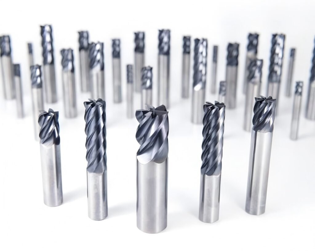
When selecting a solid carbide end mill, most machinists and buyers focus on obvious parameters: diameter, flute count, coating, or corner radius.
However, in real CNC machining, some of the most decisive factors are also the least discussed.
Two of them are:
- Helix direction
- Cutting hand (cutting edge orientation)
Why does one end mill pull chips upward while another pushes them downward?
Why does the same tool perform flawlessly on one setup but cause vibration or burrs on another?
And why do experienced engineers deliberately choose left-hand helix tools for thin or flexible parts?
This article explains helix direction and cutting hand from a mechanical and application-driven perspective, helping you understand how these design details directly affect cutting behavior, surface quality, and tool life.
What Is Helix Direction on a Solid Carbide End Mill?
How do you correctly identify helix direction?
Viewed from the front face of the end mill, if the flute extends toward the shank:
- Leaning to the left → Left-hand helix
- Leaning to the right → Right-hand helix
This definition is purely geometric and independent of spindle rotation.
Why does helix direction matter in machining?
Helix direction determines:
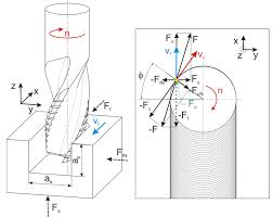
- The axial cutting force direction
- The chip evacuation path
- How the tool interacts with part rigidity and fixturing
- The tendency for vibration, chatter, or part lifting
In practical terms:
Helix direction decides whether the tool pulls the workpiece upward or presses it downward during cutting.
Right-Hand Helix vs. Left-Hand Helix: What Changes in Cutting Mechanics?
Right-Hand Helix End Mills (Industry Standard)
Right-hand helix end mills generate an upward axial cutting force.
Mechanical behavior:
- Chips are evacuated upward along the flutes
- Heat is carried away efficiently with the chips
- Cutting action feels smoother at high spindle speeds
Typical applications:
- Aluminum and non-ferrous alloys
- Deep pockets and cavities
- High-speed machining (HSM)
- General-purpose CNC milling
Left-Hand Helix End Mills
Left-hand helix end mills generate a downward axial cutting force.
Mechanical behavior:
- Chips are directed downward or laterally
- The workpiece is pressed against the fixture
- Reduced risk of part lifting during finishing
Typical applications:
- Thin plates and sheet metal parts
- Low-rigidity setups
- Finishing passes where flatness is critical
- Operations sensitive to burr formation on top edges
Helix Direction and Cutting Force Behavior
Helix Direction | Axial Force Direction | Chip Flow Direction | Typical Use Case |
Right-hand helix | Upward | Upward evacuation | Aluminum, deep pockets, HSM |
Left-hand helix | Downward | Downward / lateral | Thin parts, weak fixturing |
What Is Cutting Hand and Why Is It Often Confused with Helix Direction?
How is cutting hand defined?
To determine cutting hand:
1.Place the end mill with the bottom cutting edge facing upward
2.Look at the tool from the front
3.Observe the cutting edge orientation:
- Cutting edge facing left → Left-hand cutting
- Cutting edge facing right → Right-hand cutting
Why does cutting hand matter?
Cutting hand determines whether the tool can cut under a given spindle rotation.
- Right-hand cuttingtools are designed for clockwise spindle rotation
- Left-hand cuttingtools require counterclockwise rotation
Since most CNC machines are configured for clockwise rotation, right-hand cutting end mills dominate industrial machining.
Helix Direction vs. Cutting Hand: They Are Not the Same Thing
This is one of the most common misunderstandings.
- Helix directioncontrols force direction and chip evacuation
- Cutting handcontrols rotational compatibility
They are independent parameters and can be combined in different ways.
Common Helix and Cutting Hand Combinations
Helix Direction | Cutting Hand | Spindle Rotation | Typical Application |
Right-hand helix | Right-hand cutting | Clockwise | Standard CNC machining |
Left-hand helix | Right-hand cutting | Clockwise | Downward force, thin parts |
Left-hand helix | Left-hand cutting | Counterclockwise | Special machines, custom tools |
Right-hand helix | Left-hand cutting | Counterclockwise | Rare, niche use |
In practice, right-hand cutting + right-hand helix remains the most widely used configuration.
Why Do Some End Mills Push Chips Downward Instead of Upward?
This question is especially important in thin-walled and finishing operations.
When a right-hand cutting end mill uses a left-hand helix, it creates:
- Downward axial cutting force
- Improved workpiece stability
- Reduced burr formation on the top surface
This configuration is commonly used in:
- Aerospace aluminum skins
- Electronic housings
- Thin stainless steel covers
- Precision finishing of flat components
Often, simply changing helix direction solves stability issues without modifying feeds or spindle speed.
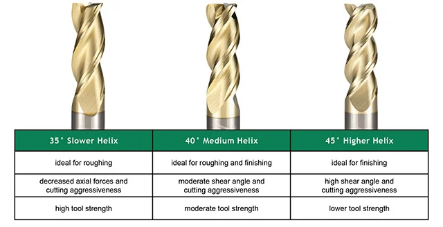
How Does Helix Angle Magnitude Change Performance?
Helix direction defines force direction, but helix angle defines force intensity and smoothness.
Typical helix angle ranges in solid carbide end mills
Helix Angle | Cutting Characteristics | Typical Materials |
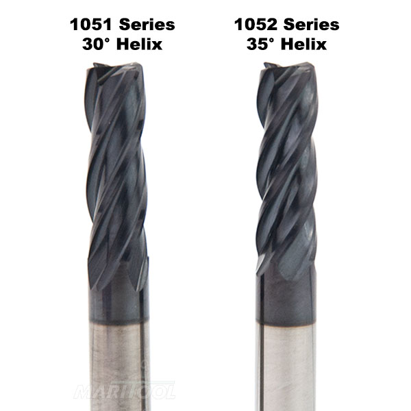
30°–35° | High rigidity, strong edge | Hardened steel, alloy steel |
38°–45° | Balanced cutting | General-purpose steel, stainless |
45°–55° | Smooth cutting, low force | Aluminum, finishing operations |
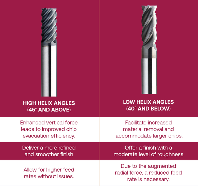
Higher helix angles:
- Reduce cutting force per tooth
- Improve surface finish
- Increase risk of chatter on weak setups
Lower helix angles:
- Increase tool rigidity
- Improve edge strength
- Reduce chip evacuation efficiency
Chip Evacuation, Heat Flow, and Tool Life: The Hidden Relationship
Helix direction strongly influences thermal behavior during cutting.
- Efficient chip evacuation removes heat from the cutting zone
- Poor chip flow increases tool–workpiece contact time
- Heat accumulation accelerates coating wear and edge chipping
Helix Direction and Heat Management
Factor | Right-Hand Helix | Left-Hand Helix |
Chip evacuation efficiency | High | Medium |
Heat removal | Efficient | Less efficient |
Tool life in aluminum | Longer | Shorter |
Stability on thin parts | Medium | High |
This trade-off explains why left-hand helix tools are rarely used for aggressive roughing, but highly effective for precision finishing.
When Should You Choose a Left-Hand Helix Tool on Purpose?
Left-hand helix tools are not niche products without purpose.
They are problem-solving tools.
Choose them when:
- Parts lift during finishing passes
- Burrs appear on the top surface
- Fixturing strength is limited
- Flatness and dimensional stability are critical
In many cases, selecting the correct helix direction delivers better results than increasing clamping force or reducing cutting parameters.
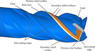
How Tool Nose Geometry Completes the Picture
While helix direction and cutting hand define macro cutting behavior, tool nose geometry defines micro-level results.
- Flat end: sharp corners, shoulders, slotting
- Corner radius: improved edge strength and tool life
- Ball nose: 3D contours and surface finishing
A stable helix configuration allows these geometries to perform consistently and predictably.

Final Thoughts: Helix Direction Is Not a Minor Detail
In solid carbide end mill design, helix direction and cutting hand are not secondary parameters.
They are core engineering decisions that influence:
- Cutting force distribution
- Chip evacuation
- Heat management
- Surface quality
- Tool life
For engineers, machinists, and technical buyers, understanding these fundamentals leads to:
- Fewer trial-and-error tool changes
- More stable machining processes
- Better alignment between tool design and application


