
Choosing the Right Drill Point Angle: How Geometry Determines Hole Quality, Tool Life, and Productivity
Table of Contents
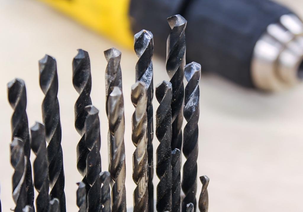
Drilling may appear to be one of the simplest machining operations, yet it remains one of the most misunderstood.
Why do some drills cut smoothly while others chatter?
Why do identical drills perform differently on different materials?
Why does one drill last thousands of holes while another fails prematurely?
In many cases, the answer starts at the tip.
The drill point angle—together with the point geometry behind it—largely determines cutting forces, chip formation, heat generation, centering behavior, and ultimately the success of your drilling operation.
There is no universal “best” point angle. Instead, optimal performance comes from selecting the right combination of point angle and point geometry for a specific material, machine setup, and production objective.
This article explains how drill point angles work, how modern geometries improve performance, and how to select the right configuration for your application.
What Exactly Is a Drill Point Angle?
The drill point angle is the included angle between the two main cutting lips at the tip of the drill.
It directly influences:
- How quickly cutting edges engage the workpiece
- Distribution of cutting forces
- Chip thickness and shape
- Strength of the cutting edge
- Heat concentration at the tool tip
However, the point angle alone does not define performance. Modern drills combine the angle with engineered point geometries that modify the chisel edge, rake angles, and clearance surfaces.
In practice, drill performance is defined by:
Point Angle + Chisel Edge Geometry + Lip Relief + Web Thickness + Coating
Why Does Point Angle Matter So Much?
The point angle determines how aggressively a drill penetrates material and how loads are distributed across the cutting edges.
General trends:
Smaller angles (sharper point)
- Lower thrust force
- Faster penetration
- Weaker cutting edge
Larger angles (flatter point)
- Stronger cutting edge
- Better wear resistance
- Higher thrust force
Choosing incorrectly can lead to:
- Edge chipping
- Premature flank wear
- Built-up edge
- Poor hole roundness
- Burr formation
- Excessive heat
Which Point Angles Are Most Common in Metal Cutting?
Two angles dominate industrial drilling:
- 118°
- 135°
They remain popular because they provide broad application coverage and work well with modern multi-facet geometries.
Basic Characteristics
Point Angle | Edge Strength | Thrust Force | Typical Materials |
118° | Moderate | Lower | Aluminum, mild steel, plastics |
135° | High | Higher | Stainless steel, alloy steel, titanium |
Why Is 118° Still Widely Used?
The 118° point angle produces a relatively sharp cutting edge. This allows easier penetration into softer materials and reduces required thrust force.
Typical advantages:
- Good cutting sharpness
- Lower axial load
- Smooth cutting action
- Economical to manufacture
Typical applications:
- Aluminum alloys
- Copper alloys
- Low-carbon steels
- Plastics
- Thin sheet materials
For general-purpose HSS drills and entry-level carbide drills, 118° remains a cost-effective solution.
However, traditional 118° conical points suffer from a wide chisel edge, which generates extrusion rather than cutting. This increases heat and reduces accuracy.
Modern 118° drills almost always incorporate split-point or multi-facet geometry to eliminate this weakness.
Why Has 135° Become the Industry Standard for Harder Materials?
A 135° point angle produces a flatter cutting face, which strengthens the cutting edge and improves resistance to micro-chipping.
Advantages:
- Stronger cutting lip
- Better wear resistance
- Improved edge stability
- Suitable for higher cutting speeds
Typical applications:
- Stainless steels
- Alloy steels
- Tool steels
- Titanium alloys
- Nickel-based alloys
Most premium carbide twist drills for steel machining today are built around 135° geometry combined with advanced split points.
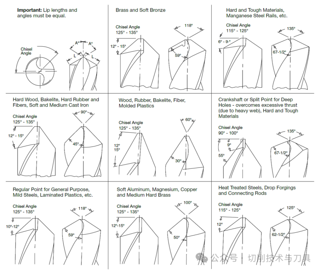
Recommended Point Angles by Workpiece Material
Material Group | Typical Hardness (HB) | Recommended Point Angle |
Aluminum alloys | 40–120 | 118° |
Copper / Brass | 60–120 | 118° |
Mild steel | 120–180 | 118° |
Medium carbon steel | 180–220 | 120°–130° |
Alloy steel | 200–300 | 135° |
Stainless steel | 180–260 | 135° |
Cast iron | 180–240 | 120°–135° |
Titanium alloys | 300+ | 135° |
Nickel alloys | 300+ | 135° |
These values are widely referenced in tooling catalogs and machining handbooks.
Is Point Angle Enough? Why Geometry Matters More Than Ever
Early twist drills relied on a simple conical point. This design creates a wide chisel edge at the center.
The chisel edge:
- Does not cut
- Pushes material
- Generates heat
- Requires high thrust force
Modern point geometries modify the chisel edge to:
- Create true cutting action
- Reduce thrust force
- Improve centering
- Enhance chip evacuation
Today’s performance gains come primarily from geometry design rather than angle alone.
What Is a Split Point (S-Point) Geometry?
Split point drills feature a thinned web and divided chisel edge.
Key benefits:
- Self-centering behavior
- Reduced thrust force
- Easier penetration
- Less walking
- Better hole position accuracy
Split points are extremely common on:
- 118° carbide drills
- 135° carbide drills
- Cobalt HSS drills
Most modern CNC drills use split-point geometry as a baseline.
What Is a Multi-Facet (Polygonal) Point?
Multi-facet points use multiple planar surfaces rather than a smooth cone.
Benefits:
- Shortened chisel edge
- Controlled rake angles
- Lower heat generation
- Stable cutting action
Compared to traditional conical points:
- Thrust force can drop by ~40–50%
- Heat generation can drop by ~50–60%
These values are frequently cited in tooling manufacturer performance studies.
What Is a Helical (Curved) Point Geometry?
Helical or S-shaped points create a curved cutting profile at the center.
Advantages:
- Excellent self-centering
- High hole roundness
- Close-to-nominal cutting diameter
Often used in:
- Precision drilling
- Thin-wall parts
- Applications without spotting
What Is Racon®-Type Geometry?
Racon-style points use continuously varying point angles from center to periphery.
Benefits:
- Very low cutting forces
- Smooth chip formation
- Extended tool life
Limitation:
- Not self-centering
- Requires guide bush or pilot hole
Often applied in deep-hole drilling systems.
What Is Bickford™-Type Geometry?
Bickford-style geometry combines:
- Split point characteristics
- Racon-style load distribution
Advantages:
- Self-centering
- High feed capability
- Long tool life
- Burr-free breakthrough
Used in high-volume production drilling.
Geometry Comparison Overview
Geometry Type | Self-Centering | Thrust Force | Typical Use |
Conical | No | High | Low-cost general drills |
Split Point | Yes | Low | Universal CNC drilling |
Multi-Facet | Yes | Very Low | High-performance drilling |
Helical Point | Yes | Very Low | Precision holes |
Racon-Type | No | Very Low | Guided drilling |
Bickford-Type | Yes | Very Low | High-feed production |
How Should Point Angle and Geometry Be Combined?
Effective combinations:
- 118° + Split Point→ Aluminum, mild steel
- 135° + Split Point→ Stainless steel, alloy steel
- 135° + Multi-Facet→ High-speed steel machining
- 135° + Helical Point→ Precision applications
- 135° + Bickford-Type→ High-feed CNC production
How Does Coating Interact with Point Geometry?
Geometry determines cutting mechanics. Coating determines thermal and wear behavior.
Common pairings:
- AlTiN or AlCrN + 135° split point → Stainless steel
- TiB2 + 118° split point → Aluminum
- Nanocomposite coatings + multi-facet point → High-speed machining
Coatings cannot compensate for incorrect geometry, but correct geometry allows coatings to reach full potential.
What Role Does Web Thickness Play?
As drill diameter increases:
- Web thickness increases
- Chisel edge widens
Modern drills use:
- Web thinning
- Split-point thinning
- Central thinning
These features directly improve performance more than changing point angle alone.
How Does Point Angle Affect Tool Life?
Higher point angles:
- Reduce edge chipping
- Lower micro-fracture risk
- Improve wear uniformity
Lower point angles:
- Sharper edge
- Higher wear rate
For carbide drills, 135° is generally preferred for tool life stability.
Typical Failure Modes from Wrong Point Selection
Symptom | Likely Cause |
Chipping | Point angle too small |
Burning | Too much thrust / poor geometry |
Walking | No self-centering geometry |
Poor roundness | Conical point |
Burrs | Wrong angle or geometry |
Product-Level Perspective: What Should Buyers Look For?
When evaluating carbide drill product series:
- Clearly specified point angle
- Clearly specified point geometry type
- Optimized web thinning
- Coating matched to material group
- Dedicated aluminum vs steel series
High-end manufacturers usually offer:
- Aluminum series → 118°, polished flute, TiB2
- Steel series → 135°, split/multi-facet, AlTiN
- Stainless series → 135°, reinforced edge, AlCrN
Practical Selection Workflow
1.Identify workpiece material
2.Choose point angle from material group
3.Choose geometry for centering and thrust control
4.Match coating
5.Set correct cutting parameters
This sequence produces far more reliable results than angle-first thinking alone.

Final Thoughts
While almost any drill can create a hole, only the correct combination of point angle and geometry can create holes efficiently, repeatedly, and economically.
Modern drilling performance is no longer defined by angle alone—it is driven by geometry engineering.
Selecting the right point design will:
- Increase tool life
- Improve hole accuracy
- Reduce cycle time
- Lower cost per hole
In high-performance machining, geometry is not a detail—it is the foundation.


