
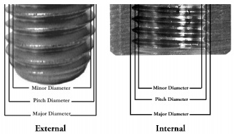
Full-Profile or Partial-Profile Threading Inserts?
Table of Contents
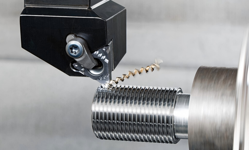
External thread turning looks simple: define the pitch, run a threading cycle, check with a gauge.
Yet in real production, threads often fail for reasons that are not obvious at first glance.
Why do some external threads show burrs on the crest?
Why do threads that pass inspection still fail early in service?
Why does tool life vary so much when machining the same material and pitch?
The answer lies in insert geometry, blank diameter control, and cutting strategy.
This article provides a practical, production-oriented guide to CNC turning of standard external cylindrical threads (mainly ISO Metric / Unified 60° threads). We focus on full-profile vs. partial-profile threading inserts, explain where each works best, and show how small process details directly affect thread strength, surface quality, and consistency.
Why Is External Thread Turning More Critical Than It Looks?
Threads are functional features, not decorative ones.
In mechanical assemblies, they must:
- Carry axial load
- Survive vibration and cyclic stress
- Provide stable and repeatable tightening torque
Unlike turning a simple diameter, thread turning involves:
- Helical, interrupted cutting
- Increasing cutting contact as depth grows
- High sensitivity to geometry and setup
A thread that “looks fine” can still suffer from:
- Stress concentration at the root
- Burrs that damage mating parts
- Inconsistent clamping force
This is why tool selection matters more than many operators expect.
What Threading Inserts Are Commonly Used on CNC Lathes?
For external threads, three tool approaches dominate:
1.Full-profile (fixed-pitch) threading inserts
2.Partial-profile (multi-pitch / universal) threading inserts
3.Hand-ground threading tools
In modern CNC production, the real choice is usually between the first two.
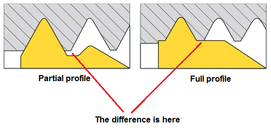
What Makes Full-Profile Threading Inserts Different?
A full-profile threading insert is designed for one specific thread pitch and standard.
It generates:
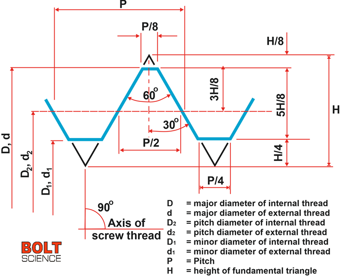
- Correct flank angle
- Defined crest truncation
- Controlled root form
Typical examples include inserts such as 16ER 3.0 ISO, 22ER 2.5 ISO, etc., depending on holder size and pitch.
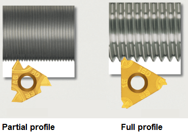
Why Do Full-Profile Inserts Produce Cleaner Threads?
Because the insert itself completes the entire thread geometry, including crest finishing.
Key advantages:
- Accurate thread height (with correct blank diameter)
- Burr-free thread crest
- Consistent thread geometry across batches
- Better compliance with ISO / DIN expectations
Typical applications:
- Batch and mass production
- Load-bearing threads
- Automotive, hydraulic, and mechanical components
- Export-oriented parts where consistency matters
If Full-Profile Inserts Are So Good, Why Use Partial-Profile Inserts?
Because flexibility is valuable.
A partial-profile (universal) threading insert forms mainly the thread flanks.
The crest and final root shape depend on cutting depth and blank diameter.
Common examples include 16ER AG60, 16ER A60, or similar universal 60° inserts.
They are widely used for:
- Job shops with many different pitches
- Prototyping and repair work
- Training environments
- Threads with moderate quality requirements
What Problems Can Partial-Profile Inserts Cause?
Two issues appear frequently in production.
1. Crest Burr Formation
Because the insert does not fully control crest geometry, excess material may remain at the top of the thread—especially on ductile steels and stainless steels.
2. Undersized or Sharp Thread Roots
When machining larger pitches with a universal insert, the resulting root radius can be smaller than the standard profile, leading to stress concentration.
These threads may still pass a gauge but show reduced fatigue strength in service.
Full-Profile vs. Partial-Profile: A Practical Comparison
Insert Type Comparison for External Threads
Feature | Full-Profile Insert | Partial-Profile Insert |
Crest finishing | Controlled by insert | Depends on blank & depth |
Burr risk | Low | Higher |
Root geometry | Standard-consistent | Can be undersized |
Pitch flexibility | One pitch only | Multiple pitches |
Production stability | Very high | Operator-dependent |
This is why full-profile inserts dominate in high-reliability applications, despite their lower flexibility.
Why Is Blank Diameter So Critical in Thread Turning?
Even the best insert cannot compensate for an incorrect blank diameter.
If the Blank Diameter Is Too Small
- Thread height is insufficient
- Crest does not fully clean up
- Burrs are more likely (especially with universal inserts)
If the Blank Diameter Is Too Large
- Crest trimming edge carries excessive load
- Insert wear accelerates
- Risk of chipping increases
A widely accepted production guideline is:
In the finishing pass, the crest trimming edge should remove about 0.03–0.05 mm radially.
This small, controlled cut ensures:
- Clean crests
- Stable cutting forces
- Longer insert life
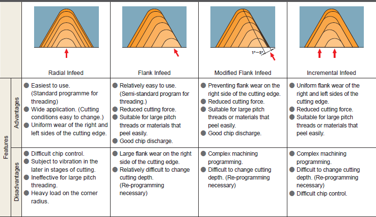
How Does Infeed Strategy Affect Thread Quality?
Ask not “Which cycle do I use?” but “Where does the cutting force go?”
Straight radial infeed loads both flanks simultaneously, increasing cutting force and chatter risk.
Flank infeed shifts most of the load to one side, improving stability.
Recommended practice:
- Right-flank infeed for right-hand threads
- Modified flank infeed for better load distribution
Benefits include:
- Reduced vibration
- Improved surface finish
- More predictable tool life
What Cutting Data Should You Start With?
Thread turning feed is fixed by pitch, so cutting speed and depth strategy become critical.
Typical Starting Cutting Speeds for External Thread Turning
Material group | Cutting speed (Vc) |
Steel (ISO P) | 80–160 m/min |
Stainless steel (ISO M) | 50–120 m/min |
Cast iron (ISO K) | 60–140 m/min |
Aluminum (ISO N) | 150–400 m/min |
Heat-resistant alloys (ISO S) | 20–60 m/min |
Always adapt speeds based on:
- Insert grade and coating
- Coolant strategy
- Machine rigidity
When Should You Choose Each Insert Type?
Application-Based Insert Selection
Application | Recommended Insert |
Mass production | Full-profile |
Load-bearing threads | Full-profile |
Export / DIN / ISO compliance | Full-profile |
Prototyping | Partial-profile |
Many pitches, low volume | Partial-profile |
Training | Partial-profile |
There is no “universal best insert”—only correct choices for specific applications.
Common Problems and Practical Solutions
Crest burrs?
→ Check blank diameter, reduce finishing load, or switch to full-profile inserts.
Short thread life in service?
→ Inspect root geometry; universal inserts on large pitches are a common cause.
Inconsistent tool life?
→ Look at crest trimming load, infeed method, and insert grade suitability.
Final Thoughts: What Defines a Reliable External Thread?
A reliable external thread is defined by:
- Correct geometry
- Controlled crest finish
- Reasonable root stress distribution
- Stable, repeatable machining conditions
In many production environments, the most reliable combination is:
- Full-profile insert matched to pitch
- Controlled blank diameter
- Flank infeed strategy
- Conservative, stable cutting parameters
Thread turning is not just a CNC cycle—it is a process discipline.


