 Skip to content
Solid Carbide End Mill Cutter Geometry Explained:Why Rake Angle, Helix Angle, and Grinding Decide Your Machining Results
Table of Contents
When selecting an end mill cutter, many buyers still focus on only two things: diameter and material hardness. But experienced machinists know that the real performance of a solid carbide end mill cutter is determined not by size alone, but by its geometry and grinding quality.
Why does one carbide end mill last twice as long as another with the same diameter?
Why does surface finish vary dramatically even under identical cutting parameters?
And why do some tools chatter while others cut smoothly at high speed?
The answer lies in end mill cutter geometry.
In this article, we take a deep, practical look at:
- What end mill cutter geometry really means
- How rake angle, relief angle, helix angle, and flute number affect cutting behavior
- How professional grinding and regrinding improve tool life
- How to choose the right geometry for steel, stainless steel, aluminum, and hardened materials
This guide is written for engineers, CNC programmers, and tool buyers who want reliable, repeatable machining results—not just generic tools.
What Is an End Mill Cutter, and How Does It Really Work?
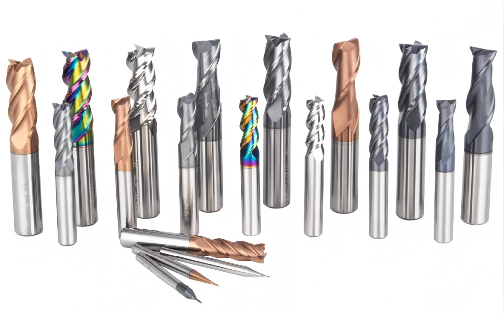
An end mill cutter is a rotary cutting tool used in milling operations to remove material from a workpiece. Unlike drills, end mills can cut laterally, radially, and axially, making them one of the most versatile cutting tools in CNC machining.
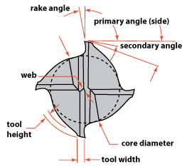
A typical solid carbide end mill cutter consists of:
- A shank for tool holding
- Helical flutes for chip evacuation
- A peripheral cutting edge (main cutting edge)
- An end cutting edge (secondary cutting edge)
What separates a high-performance tool from an average one is how these elements are designed and ground together.
Why Is End Mill Cutter Geometry More Important Than Tool Material?
Carbide as a material already offers:
- High hardness
- Excellent wear resistance
- Thermal stability
However, geometry determines how that material behaves during cutting.
A poorly designed geometry can cause:
- Excessive cutting force
- Built-up edge
- Poor chip evacuation
- Chatter and premature tool failure
A well-optimized geometry, by contrast, delivers:
- Stable cutting
- Lower spindle load
- Better surface finish
- Longer tool life
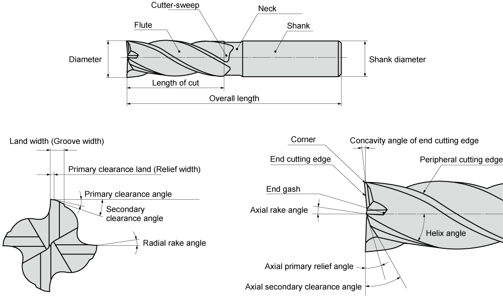
The Key Geometric Angles of a Solid Carbide End Mill Cutter
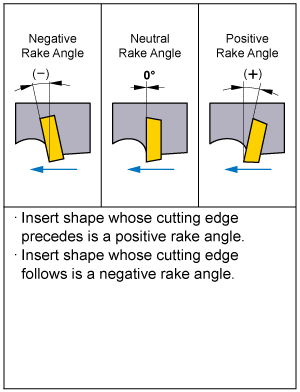
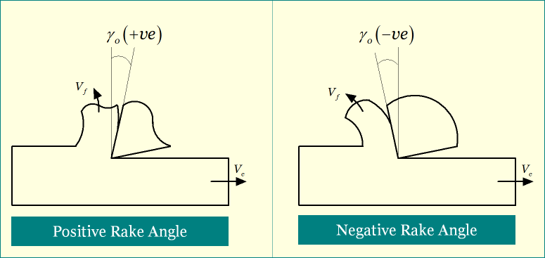
1. What Is the Rake Angle, and Why Does It Matter?
The rake angle controls how aggressively the cutting edge engages the material.
Positive rake angle
- Sharper cutting edge
- Lower cutting force
- Ideal for aluminum and stainless steel
Negative rake angle
- Stronger edge
- Better resistance to chipping
- Suitable for hard or abrasive materials
Key insight:
A sharper rake angle improves cutting efficiency but reduces edge strength. Geometry must balance sharpness and durability.
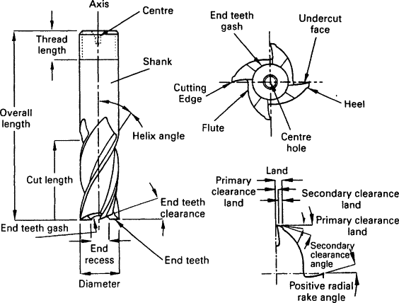
2. What Is the Relief Angle, and How Does It Reduce Tool Wear?
The relief angle prevents the tool’s flank from rubbing against the machined surface.
Functions of proper relief angle:
- Reduces friction and heat
- Prevents surface burnishing
- Improves surface finish
Relief angles are typically smaller for:
- Roughing tools
- High-hardness materials
And larger for:
- Ductile materials
- Finishing operations
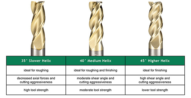
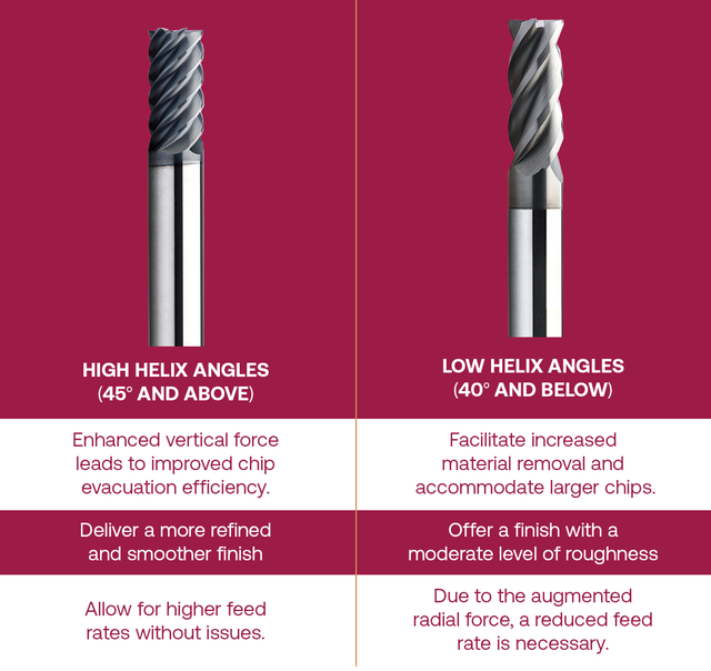
3. Helix Angle: Why 30° and 45° Behave So Differently
The helix angle determines chip flow direction and cutting smoothness.
Comparison of Common Helix Angles
Helix Angle | Cutting Characteristics | Typical Applications |
30° | High rigidity, stable cutting | Carbon steel, cast iron |
35–40° | Balanced performance | General-purpose machining |
45° | Smooth cutting, sharp entry | Stainless steel, superalloys |
Rule of thumb:
Higher helix = smoother cut, higher axial force
Lower helix = stronger tool body, better stability
How Many Flutes Should an End Mill Cutter Have?
Flute number affects chip evacuation, rigidity, and surface finish.
Flute Count Comparison
Flute Number | Advantages | Limitations | Typical Use |
2 flutes | Excellent chip evacuation | Lower rigidity | Slots, soft materials |
3 flutes | Balanced chip space | Limited for steel | Aluminum, plastics |
4 flutes | High rigidity, good finish | Reduced chip space | Steel, general use |
6 flutes | Excellent finish | Poor chip evacuation | Finishing, shallow cuts |
For manufacturers processing multiple materials, a 4-flute solid carbide end mill cutter is often the most economical and versatile choice.
End Mill Cutter Geometry for Different Materials
Choosing the wrong geometry for a material is one of the most common machining mistakes.
Geometry Selection by Workpiece Material
Material | Recommended Geometry | Reason |
Aluminum | High rake, 3 flutes, 45° helix | Prevent chip welding |
Carbon steel | Moderate rake, 4 flutes, 30° helix | Balance strength and finish |
Stainless steel | Sharp rake, 45° helix | Reduce cutting force |
Hardened steel (HRC50+) | Reinforced edge, smaller relief | Prevent edge chipping |
This is why professional manufacturers often offer material-specific end mill series, rather than one “universal” tool.
Why Grinding Quality Defines the Performance of a Carbide End Mill Cutter
Even the best geometry design fails without precision grinding.
Grinding determines:
- Edge sharpness
- Angle accuracy
- Consistency between flutes
End Face Grinding: Why Flatness Matters
Before grinding cutting angles, the end face must be ground perfectly perpendicular to the tool axis.
If not:
- One flute cuts more than others
- Tool vibration increases
- Surface flatness deteriorates
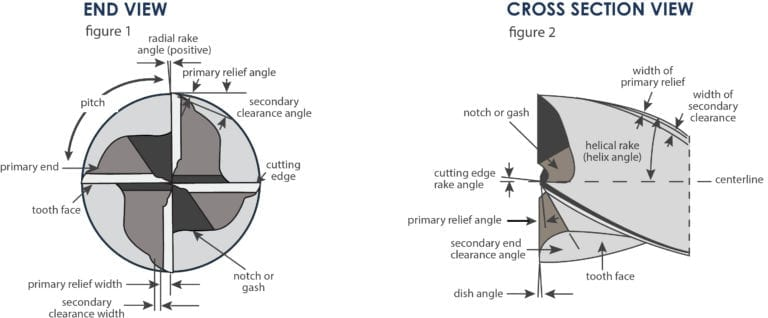
What Grinding Angles Are Typically Used?
Grinding Parameter | Typical Range |
Primary relief angle | 6° – 8° |
Secondary relief angle | 30° – 45° |
Cutting edge inclination | 1° – 3° |
Critical principle:
All cutting edges must slope slightly toward the center, never outward. A convex center guarantees poor surface finish.
Can a Carbide End Mill Cutter Be Reground Successfully?
Yes—if done correctly.
Professional regrinding can:
- Restore cutting performance
- Reduce tooling cost
- Extend tool lifecycle
However, poor regrinding often introduces:
- Unequal flute height
- Incorrect angles
- Excessive taper
Reground tools should be used for:
- Secondary operations
- Less demanding tolerances
End Mill Cutter vs Face Mill Cutter: What’s the Difference?
Feature | End Mill Cutter | Face Mill Cutter |
Cutting direction | Axial + radial | Primarily radial |
Typical diameter | Small to medium | Medium to large |
Application | Slots, profiles, pockets | Facing large surfaces |
Understanding this difference prevents incorrect tool selection and machining inefficiency.

Final Thoughts: Geometry Is Not Optional—It’s Decisive
A solid carbide end mill cutter is not just a consumable—it is a precision-engineered cutting system.
When geometry is optimized:
- Cutting forces are controlled
- Tool life increases
- Machining becomes predictable
For CNC shops and industrial buyers, understanding end mill cutter geometry and grinding principles is no longer optional—it is essential for competitiveness.
Looking for Application-Specific Carbide End Mill Cutters?
Modern machining increasingly demands material-optimized end mill designs, such as:
- High-performance series for stainless steel
- Reinforced-edge tools for hardened steel
- High-helix cutters for aluminum
Choosing the right geometry is the first step toward stable, efficient machining.


