 Skip to content
End Mill Geometry That Actually Matters: Flutes, Helix, Rake & Relief
Table of Contents
If two end mills are the same diameter, same coating, and even the same carbide grade, they can still cut completely differently. One runs quietly and holds size; the other chatters, welds chips, or chips the corner in the first minute.
The reason is end milling cutter geometry—the hidden set of angles and shapes that decides how the tool forms chips, how much force it creates, where heat goes, and how stable it is in the cut.
This guide is written for practical selection in steel, stainless steel, aluminum, and general machining—whether you call it an end milling cutter, a milling end mill cutter, a cutter milling end, or a milling machine end mill cutter. You’ll also see when an end milling cutter 20 degrees helix can outperform higher-helix tools.
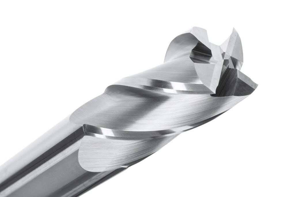
What is end milling cutter geometry?
End milling cutter geometry is the combination of:
- Cutting edge shape(corner form, edge radius, honing)
- Angles(helix, rake, relief/clearance)
- Structural dimensions(core thickness, flute depth, neck design)
- Chip-control features(gash, flute polish, chip splitters on roughers)
In real machining, geometry is not “theory”—it’s the reason you see:
- Longer or shorter tool life
- Smooth or torn surface finish
- Stable cutting or chatter
- Clean evacuation or built-up edge (BUE) and chip packing
A simple rule: Match geometry first. Then choose coating and brand series.
Flutes: what brands tune differently
Flute count is not only about “finish vs roughing.” It’s a balance of:
- Chip space
- Edge engagement (how many teeth in the cut)
- Tool stiffness (core size)
- Heat and evacuation
- Chatter sensitivity
Flute count selection
Flutes | Typical best use | Why it works | Common failure if misused |
2 | Aluminum, non-ferrous, plastics; slotting | Maximum chip space, low risk of packing | In steel: edge chipping + poor finish, can vibrate at low engagement |
3 | Aluminum + light steel; high-feed roughing on rigid machines | More edges than 2-flute but still good chip room | In gummy materials: BUE if edge prep/coating not matched |
4 | General steel, alloy steel, many “universal” cuts | Balanced chip room and finish; good stiffness | In deep slots: chip packing if feed/speed or coolant is wrong |
5–6 | Finishing, hard milling, trochoidal, small radial engagement | More edges = smoother cut, better load sharing | In slotting: chips have nowhere to go → heat, packing, breakage |
7+ | Specialized finishing / rigid setups | Very stable finish at light cuts | Any heavy chip load → instant overload |
Brand-series differences you can actually feel:
Two “4-flute” tools can differ massively because of flute depth, core thickness, edge prep, and helix. Many premium series quietly optimize core-to-flute ratio and edge preparation for specific materials (steel vs stainless vs aluminum), even if the flute count looks identical.
Helix angle: high helix vs low helix
Helix angle controls how the tool “pulls” into the material and how it lifts chips up the flute.
- Higher helix (e.g., 35°–45°):smoother cutting, better chip lift, lower cutting forces per toothin many cases.
- Lower helix (e.g., 20°–30°):stronger edge, less axial pull, often more stable in interrupted cuts.
When an end milling cutter 20 degrees helix is better
A true end milling cutter 20 degrees (low helix) can outperform higher-helix tools when:
- Harder materials / tough scale(the edge needs support)
- Interrupted cutting(keyways, cast surfaces, cross-holes, welds)
- Thin walls(less “suction” and part deflection)
- Chatter-prone setups(long reach, weaker holders, less rigid machines)
When high helix is better
Higher helix wins when:
- Aluminum and non-ferrous(chip evacuation and anti-welding)
- Continuous cuts(pockets, profiling with stable engagement)
- High-speed finishing(better surface and lower vibration)
What changes in the cut
Helix angle | Cutting “feel” | Axial pull | Edge strength | Chip evacuation | Best matched materials |
~20° | Firm, stable | Low | High | Medium | Hardened/tough alloys, interrupted cuts, thin walls |
~30° | Balanced | Medium | Medium-high | Medium-high | General steel, mixed work |
~35–45° | Smooth, quiet | Higher | Medium | High | Aluminum, continuous cuts, finishing |
If your milling machine end mill cutter chatters in a pocket, try reducing axial pull: lower helix, thicker core, shorter stickout, or switch from full-slotting to dynamic paths.
Rake angle & edge prep
Rake angle affects how easily the edge shears material. But rake alone is not the whole story—edge preparation (hone/chamfer) determines whether the edge survives.
Sharp edge (minimal hone)
Pros:
- Lower cutting forces
- Cleaner cut in aluminum
- Less rubbing at low chip loads
Cons:
- More likely to micro-chip in steel/stainless
- Sensitive to runout and vibration
Honed edge (controlled edge radius)
Pros:
- Much better resistance to chipping in steel and stainless
- More stable at higher temperatures
- Better life in interrupted cuts
Cons:
- Needs sufficient chip load to avoid rubbing
- Can increase cutting forces on low-power machines
A realistic “shop example”: In medium hardness steel (end milling cutter hrc50 as a working hardness example), a too-sharp edge may chip quickly if runout or vibration is present. A modest hone often extends life significantly, especially in roughing or interrupted engagement.
Relief angle: clearance vs strength
Relief (clearance) angle is the “space” behind the cutting edge. It prevents rubbing—but too much relief weakens the edge.
- Higher relief:less rubbing, cooler cutting at light loads, but weaker edge.
- Lower relief:stronger edge for heavy loads, but can rub/heat if chip load is too low.
Practical takeaway:
If you see burn marks + rapid flank wear, your tool may be rubbing: relief too small for your conditions or your chip load is too low. If you see edge chipping, relief may be too aggressive for the material/setup.
Core thickness & chip space: strength vs evacuation
Core thickness is the “spine” of the end mill.
A thicker core:
- Resists deflection (better size control)
- Reduces chatter
- Supports the cutting edge
But it also reduces flute volume, which can cause:
- Chip packing in slots and deep pockets
- Heat buildup
- Built-up edge in aluminum
what the chips are telling you
- Corner chipping:edge too sharp, too much vibration, or too high engagement at the corner
- BUE / welded chips:geometry too “closed,” wrong coating/finish, too low speed, or insufficient evacuation
- Burnt edges:rubbing (chip load too low), poor coolant delivery, or chip recutting
- Sudden breakage in slots:chip packing → hydraulic lock → snap
Practical selection cheat sheet
Below is a fast selection matrix you can paste into your internal tooling guide. It’s written for common carbide end mill series structures: 2-flute for aluminum, 4-flute for steel, and dedicated stainless/hard-milling variants.
Material × operation × machine rigidity → recommended geometry
Material | Operation | Machine/setup | Recommended geometry | Notes |
Aluminum | Slotting / deep pocket | Any (esp. limited coolant) | 2–3 flutes, high helix, polished flutes, sharp edge | Prioritize evacuation; avoid 5+ flutes in slots |
Aluminum | Profiling / finishing | Rigid | 3 flutes, high helix, light hone optional | Improves finish while keeping chip room |
Steel (general) | Roughing | Medium rigidity | 4 flutes, ~30° helix, thicker core, honed edge | Stable “universal” choice |
Steel (general) | Finishing | Rigid | 4–6 flutes, higher helix, controlled hone | Use light radial engagement for best results |
Stainless | Roughing | Medium rigidity | 4 flutes, strong core, positive rake but honed edge | Stainless punishes weak edges; keep chip load adequate |
Stainless | Finishing | Rigid + good coolant | 5–6 flutes, stable core, fine edge prep | Avoid chip recutting; manage heat |
Hardened steel | Light cuts / finishing | Rigid only | 4–6 flutes, lower helix (20–30°), strong edge prep | Low helix often reduces chatter and chipping |
Thin-wall parts | Any | Chatter-prone | Lower helix (including 20°), thicker core, fewer flutes | Reduce axial pull and vibration |

what “a series” should mean
On a tooling website, a “series” should not be marketing decoration—it should signal geometry intent.
A practical series layout that matches real geometry choices looks like this:
- 2-flute aluminum series:high helix, polished flutes, sharp edge, generous flute volume
- 4-flute steel series (e.g., 55HRC general purpose):balanced helix (~30°), stronger core, controlled hone
- Stainless-optimized series (e.g., 60HRC stainless):tougher edge prep, stable core, geometry that resists work-hardening issues
- Hard milling series (e.g., 65HRC class):stronger edge, often lower helix options, high thermal stability
That’s also how buyers interpret a catalog: they’re not only buying “carbide,” they’re buying geometry decisions already made for them.
Conclusion
Geometry is the first lever. Coating is the second. Brand is the third.
If you want predictable results: match end milling cutter geometry to the chip problem you actually have—evacuation, chatter, corner failure, or heat—then choose the coating and series that supports that geometry.
FAQ
1) What is end milling cutter geometry?
End milling cutter geometry is the combination of flute design, helix angle, rake and relief angles, core thickness, corner form, and edge preparation that determines cutting forces, chip evacuation, stability, finish, and tool life.
2) What does helix angle do (and what about 20 degrees)?
Helix angle changes chip lift and axial pull. Higher helix usually evacuates better and cuts smoother, especially in aluminum. A 20-degree low helix reduces axial pull and supports the edge—often better for interrupted cuts, thin walls, chatter-prone setups, and tougher/harder materials.
3) How many flutes should I use for steel vs aluminum?
For aluminum, 2–3 flutes are common because chip space matters most. For steel, 4 flutes are the most universal balance. For finishing or light radial engagement, 5–6 flutes can improve finish—but avoid high flute counts in deep slotting.
4) Why does my milling machine end mill cutter chatter?
Common causes are excessive stickout, weak holders, poor engagement strategy (full-slotting), or geometry that creates too much axial pull (high helix) for the setup. Solutions include shortening stickout, reducing radial engagement, using a lower helix, increasing core strength, or switching to dynamic toolpaths.
5) How do I read an end milling cutter diagram quickly?
Check (1) corner form (sharp vs corner radius), (2) flute volume, (3) core thickness, (4) gash/center cutting, and (5) edge prep (sharp vs honed). These predict most failure modes before you even cut.
6) What causes built-up edge (BUE) and chip welding?
Usually insufficient chip evacuation, wrong edge prep (too blunt at too low chip load), incorrect speeds/feeds, or inadequate coolant/air blast. Polished flutes, sharper edges, higher helix, and proper chip load help—especially in aluminum.
7) Is a sharper edge always better?
No. Sharp edges cut with lower force but chip more easily in steel/stainless, especially with runout or vibration. A controlled hone often increases tool life significantly in tougher materials.
8) Do I choose coating or geometry first?
Geometry first. Coating can improve heat and wear resistance, but it cannot fix a flute/core/helix mismatch that causes chip packing or chatter.


