
Drill Rake Angle (γ): Definition, Distribution, and How to Optimize It for Real-World Holes
Table of Contents
High-quality holes start at the cutting edge—literally. For twist drills and indexable/carbide drill designs, the rake angle (γ) governs chip formation, cutting forces, heat, and surface integrity. This in-depth guide translates geometry into shop-floor settings you can actually use. We’ll define rake angle precisely, show how it varies along a drill’s cutting edge, explain the levers that shift it (helix, point/lead, lip relief), and lay out practical optimization moves such as chisel-edge thinning and flute reshaping. Tables and examples are included for quick setup, and we weave in laboratory- and shop-validated data points throughout.
What the Rake Angle Is—And How to Measure It
Definition. The drill rake angle γ at any point on the main cutting edge is the angle between the tool’s rake face and a reference plane in the orthogonal plane (principal section) passing through that point. In other words, it quantifies how “open” the rake face is to the oncoming chip at that specific location along the edge.
Where we measure it. The conventional symbol γ₀ denotes the rake measured in the principal section at a selected point on the main cutting edge. On a standard twist drill this depends jointly on the helix angle β, the principal (lead) angle κᵣ, and the lip (end-face) inclination λᵣₓ.
Geometry relationship. For a selected radius RxR_xRx (distance from the drill axis to the point on the main cutting edge) and the drill radius RRR, an analytical expression for the local rake is:
tan(γ_ox) = (R_x · tanβ) / (R · sinκ_rx) − tanλ_rx · cosκ_rx
Where:
RxR_xRx: selected point radius
RRR: drill radius
βββ: helix angle
κrxκ_{rx}κrx: principal angle at the selected point
λrxλ_{rx}λrx: end-face lip inclination at that point
This equation captures how rake is not uniform along the edge. It increases with larger helix angle and decreases near the chisel/center where geometry degenerates.
Symbols and Measurement Planes
Symbol | Meaning | Practical note |
γ, γ₀, γ_ox | Local rake angle in principal (orthogonal) section | Determined point-by-point along the cutting edge |
β | Helix angle | Larger β → larger rake (but weaker edge) |
κᵣ, κ_rx | Principal (lead) angle at the point | Affects projection of flute geometry into the principal section |
λᵣₓ | Lip inclination in the end face | Negative λ drives chips toward the finished wall |
R | Drill radius | Half of drill diameter |
Rₓ | Selected radius along the edge | From Rₓ ≈ R at outer corner to Rₓ → 0 near chisel |
Drill Bit Product
Catalog
Click the button below to view our DIN milling cutters catalog and explore detailed product specifications to make the best choice.

The Rake Angle Is Not Constant: Distribution Along the Edge
Real drills don’t cut with one rake angle—they cut with a distribution:
Outer margin (near Rₓ ≈ R): Rake is maximally positive because the helix is fully developed. Typical values can reach +30° on standard twist drills. Chips are thinner and curl reliably; cutting is sharp, forces are lower.
Toward the web/center: As you move inward, geometry projects less favorably. Rake decreases progressively, crossing zero and becoming negative as you approach the chisel. Around the drill heart, local rake can be ≈ −30°; cutting conditions deteriorate and the action transitions toward extrusion.
At the chisel edge: The chisel is not a true cutting edge; it plows. Measured local rake at the chisel can be γ₀ψ ≈ −54° to −60°. This region contributes a disproportionate 45–55% of total thrust despite representing a tiny fraction of the circumference.
Practical takeaway: the outer 30–40% radius does most of the “clean” cutting. Everything near the center must be optimized or relieved to avoid unnecessary thrust, heat, and work-hardening.
Typical Rake Distribution on a Standard Twist Drill
Location on edge | Typical local rake γ | Cutting behavior | Force contribution |
Outer corner (near margin) | up to +30° | Sharp cutting, good chip flow | Low share of thrust |
Mid-radius | around 0° to −10° | Mixed cutting/extrusion | Moderate |
Near web | ≈ −30° | Predominantly extrusion | High |
Chisel edge | −54° to −60° | Plowing/indentation | 45–55% of total thrust |
What Controls Rake: The Three Big Knobs
Helix angle β
Increasing β increases γ (more positive rake), improving sharpness and flow in ductile materials—but reduces edge strength and can promote burrs or edge crumbling in hard/abrasive materials.
Typical choices: β ≈ 30–40° for aluminum/alloys; β ≈ 18–30° for steels.
Point (included) angle 2φ and principal angle κᵣ
A smaller point angle (e.g., 90°) lengthens the cutting lips, spreads the workload, and may reduce thrust on thin sections. However it exacerbates rake non-uniformity and can worsen wandering if rigidity is limited.
A larger point angle (118–140°) shortens lips, stiffens the edge, and is common for steels and hard cast irons.
Lip inclination λᵣₓ (end-face rake orientation)
Negative lip inclination directs chips toward the already machined wall—great for central evacuation in some cases, but it can scratch the bore if chip control is poor.
Positive inclination improves chip ejection in ductile materials but reduces edge strength.
Material pairing
Soft, ductile materials (Al, Cu): respond to high positive rake (≈ +25° to +35°) and high helix.
Hard, brittle or work-hardening materials (Hardened steel, CI): need small or even negative rake (0° to −15°) to protect the edge and avoid micro-chipping.
Recommended Geometry Tendencies by Material
Material group | Rake tendency (γ at outer region) | Helix β range | Point angle 2φ | Notes |
Aluminum, copper, soft plastics | +25° to +35° | 30–40° | 90–118° | Maximize sharpness & chip space; polish flutes |
Low/medium carbon steels | +10° to +20° | 20–30° | 118–130° | Balance sharpness with strength |
Stainless, nickel alloys | +5° to +15° | 20–30° | 130–140° | Control work hardening; focus on chipbreakers |
Cast iron | 0° to +10° | 18–25° | 118–135° | Edge strength over sharpness |
Hardened steels | 0° to −15° | 18–25° | 130–140° | Favor strong micro-geometry; consider carbide |
Why the Center Is a Problem—And How to Fix It
Because the rake collapses to large negatives near the center, the chisel edge plows rather than cuts. That’s why thrust skyrockets and heat concentrates. The cure is geometric intervention:
Chisel-edge thinning / web thinning
Shorten the chisel dramatically (for example, to 1/5–1/7 of its original length for “gun drill”-style grinds).
Regrind to increase local rake from ≈ −60° up toward −15° to 0°.
Result: large drop in axial force, better centering, reduced work-hardening at the hole entrance.
Special flute forms
Parabolic flutes enlarge chip space, reduce friction, and keep rake more positive along the edge.
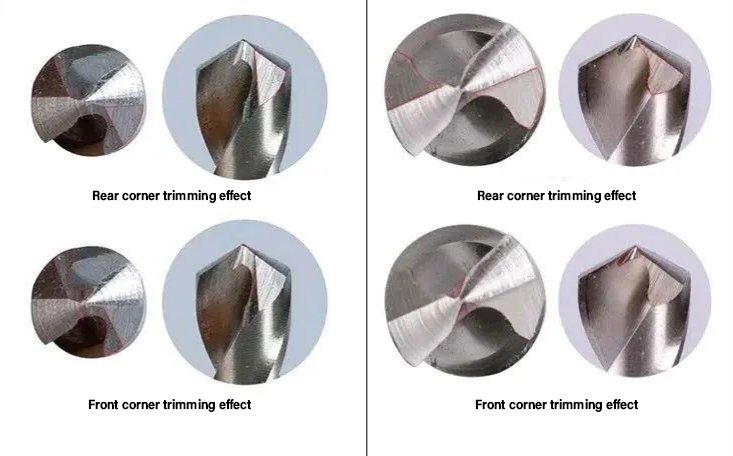
Crescent/moon-shaped thinning (a.k.a. “split point” or “four-facet” variants) improves rake uniformity and self-centering.
Lip relief & micro-geometry
Appropriate primary/secondary relief avoids rubbing.
Micro-honed edges defend against micro-chipping on hard materials while keeping the effective rake close to target.
Effect of Chisel-Edge Optimization
Action | Local rake at chisel | Thrust | Hole quality | Notes |
Standard chisel | −54° to −60° | Very high | Risk of burnish, walk | Baseline |
Thinning to 1/5–1/7 length | ≈ −15° to 0° | Much lower | Better centering, less work-hardening | Requires accurate regrind |
Split-point / Four-facet | Closer to 0° | Lower | Improved self-centering, roundness | Excellent for thin sheets & hard steels |
Carbide vs. HSS: How Rake Choices Differ
Standard HSS twist drills benefit from more positive rake at the margin to stay sharp at lower speeds, with optimized thinning to handle thrust.
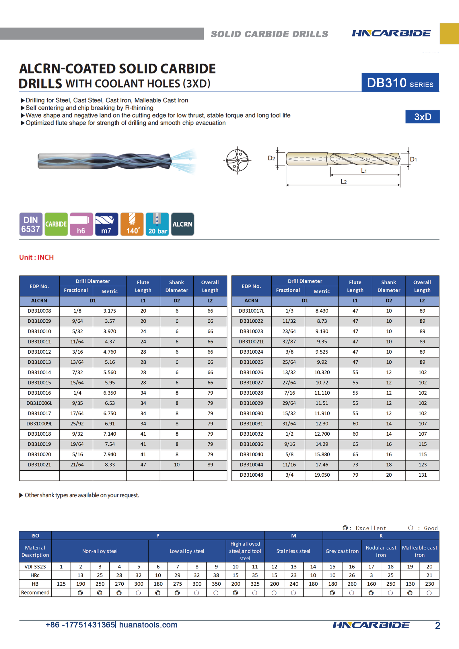
Carbide drills (solid or insert) typically use smaller positive rake (≈ 12–25° at the outer region) to protect a harder, more brittle edge. Combined with high-performance coatings (TiAlN/AlTiN, AlCrN, etc.) and engineered flute polish, they deliver long life in steels and cast irons.
In hardened steels and abrasive irons, neutral to slightly negative effective rake at the working edge plus micro-hone is common; chip formation is then managed with chipbreaker lands rather than raw rake.
Application Playbook
Standard twist drill in steel (general purpose)
β: 20–30°
2φ: 118–130°
Outer-edge γ: up to +30°, decreasing toward center
What to watch: Without thinning, the chisel generates 45–55% thrust. Regrind split point when power or straightness is a concern.
Aluminum and non-ferrous
β: 30–40°
Outer γ: +25° to +35°
Flutes: Parabolic or highly polished; wide chip gullets
Risk: Built-up edge—use high positive rake with sharp, polished lands and adequate lubricant.
Hardened steels / hard cast irons
γ target: 0° to −15° (outer region) with micro-hone
β: 18–25°; 2φ: 130–140°
Chisel: Aggressive thinning to reduce thrust; consider solid carbide with tailored chipbreakers
Coolant: Directed high-pressure through-coolant preferred; intermittent coolant can crack carbide.
Thin sheets & stacked laminations
Smaller point angle (e.g., 90–100°) reduces burr lift; split-point for accurate self-centering and minimal thrust.
Integrating Rake with Process Variables
Geometry is half the story; process conditions finish it:
Feeds & Speeds: Positive rake lowers cutting force, allowing higher feed before rubbing. Negative rake protects the edge but demands adequate feed to avoid glazing. If the drill squeals or polishes the entry, increase feed until the chip forms cleanly.
Coolant strategy: Chip evacuation rules. Through-coolant with parabolic flutes can exploit high rake without clogging. In gummy materials, a small increase in rake without coolant won’t help—prioritize lubrication.
Runout & concentricity: With high positive rake, even 10–15 μm runout dumps all the work on a single lip; hole size grows and one edge burns. Keep TIR tight.
Pilot holes & spotting: When center thrust is high, spotting or pilot drilling reduces skidding; combine with split-point to minimize required pilot size.
Worked Example—Turning Geometry Into Results
Task: Drill Ø8 mm through holes in low-carbon steel on a vertical machining center. Existing HSS drill walks and shows high spindle load.
Symptoms: Heavy thrust, bell-mouthed entry, blueing at the chisel.
Fix plan guided by rake distribution:
Replace GP drill with split-point, polished flute HSS or TiN-coated HSS.
Maintain β≈30° and outer γ≈+25–30° for sharp cutting.
Thin the web so the chisel is 1/5–1/7 original length; local rake improves from roughly −60° → −15° to 0°.
Increase feed until chips form crisp 6–10 mm spirals; reduce thrust by 20–30% compared with baseline.
Result: straighter holes, lower temperature, improved tool life.
Alternative for production: Solid carbide with 12–20° effective outer rake, tailored chipbreaker, and through-coolant. Keep point angle near 130° to stiffen lips and reduce wander at high penetration rates.
Practical Optimization Methods
Chisel-edge geometry: Thin it; split it; keep it short.
Flute form & surface: Parabolic for soft materials; crescent/engineered thinning for center relief; polish to prevent BUE.
Material matching:
Al/Cu: big γ, big β, big chip space.
Steels: moderate γ, robust edge, 118–130° point.
Hardened/Cast: small/negative γ, strong hone, 130–140° point.
Lip inclination λ: Avoid strongly negative values that scrape the bore unless chip control requires it; manage with chipbreakers instead.
Coatings: Pair rake with coatings that preserve edge sharpness (e.g., AlCrN for steels, DLC for Al).
Regrind discipline: Keep geometry symmetric; unequal rake across lips doubles eccentric force.
Special Notes for Carbide Drilling in Hard Materials
Edge micro-geometry (hone radius 10–25 μm) dramatically changes the effective rake at the very edge. A slightly honed, small-positive rake behaves more like neutral rake under load—but is far more durable.
Use neutral to slightly negative rake plus a chipbreaker land to force short, controlled chips.
Combine with point angle 130–140°, web thinning, and through-coolant.
For deep holes (L/D ≥ 8): flute polish and coolant flow trump raw rake—without evacuation the best rake simply clogs.

Conclusion
Rake angle is not a single number on a drawing; it is a field that changes from the drill’s rim to its heart. Understanding that distribution—and how helix, point geometry, and lip inclination steer it—lets you tune thrust, chip shape, and bore quality with confidence. Start by optimizing the chisel, choose rake by material class, and keep the flutes honest with the right form and a polished path. Do that, and your holes will run cooler, straighter, and faster—no magic required.


